The Test Equipment
Referring to the pictures above, here’s a basic
description of devices pictured, and some not:
TV-7/U - (Not pictured) Completely gone through and calibrated to within 1.5% of book spec on all counts. Replaced all small resistors with higher quality 1W 1% precision units. Other resistors were still ok, just in need of adjustment. I generally use this for rectifier testing because it does a satisfactory job in that respect. I will setup the main tester for rectifier tests at full voltage/current at a later date when I can integrate more through rectifier testing (thoroughly testing a rectifier, tube or solid state, is far more complicated than you might think!) I also have downloaded and printed out on 8.5" x 11" paper the most full, updated version of test data for this machine. Hint: You can steal data not appearing in the TV-7 data from the TV-10 data book, you just have to convert the minimum readings to TV-7 nomenclature (i.e. - micromhos to 0-120 scale readings). And I did just so!
Lambda 12VDC regulated supply - Behind the other supplies (Not pictured). Used to power all the 12V muffin fans I added to cool the pass tubes on the supplies with no cooling.
Power amplifier with full-range speaker - (Not pictured) Used for noise tests.
Fluke 8000A - Used for all
measurements. The manual is here.
Wavetek 178 Programmable waveform synthesizer - (Not pictured) Used as a
precision oscillator for all transconductance and gain measurements. Will be used later for other more interesting tests like determining cathode interface resistance! And yes, this sort of thing is fun to me.
California Instruments 751TC Power
Source with 800T Oscillator plug-in - Currently out of commission Used for some high power filaments,
positive grid drive related tests, and power output tests. It has an output
capable of 250VAC at up to 750VA. (I've had this unit sitting around for years
just itching to be used for something!)
Brandenburg 475R - This unit is
used for negative bias. It is capable of a regulated maximum of about 1100VDC.
Power Designs 6150 - 0-60VDC at up
to 15A supply, used for auxiliary voltages, positive bias, filament, low plate
voltages, etc.
HP Harrison 6428B - Regulated
0-22V at up to 45A, used for filament voltage.
HP 712B - Regulated 0-500VDC, modified to be used at up to 300mA
EM Regatron (Military) - Regulated 0-600VDC at 400mA.
Fluke 301C - Precision regulated 0-1kV at 400mA. This unit has been many years in the making. Made in 1956, it uses a bank of switches, all utilizing .01% precision wirewound resistors, to aid in achieving accuracy of .01VDC on the output! Unfortunately, when received, it was in deplorable condition and I have been working on it intermittently for a few years as it required a total restoration. It also required a few not-so-easy to locate parts, like an ac/dc chopper (which compares the internal standard cell to a voltage in the control circuit), matched thyristors, and a mercury battery (which was easily replaced with a long-life lithium and a pot since its in a high impedance grid bias circuit for a 6AU6). I wont go into the details of it, but suffice to say it required A LOT of work to get it up to spec!
Kepco 615B - Regulated 0-600VDC at 300mA.
Stray items include a
hand held multimeter for checking voltages at the tube pins (VERY IMPORTANT!), various plate or grid caps, special patch wires for tubes with no caps and for coaxial & lighthouse tubes, adapter for submini tubes, adapter for 5 & 7 pin nuvistors, adapter for 2C39, grid stopper resistors, squirrel cage blower motor assembly for tubes requiring forced air cooling, and a TI-85 graphing calculator. Data books on hand include the RCA RC-30, 1958 Vade Mecum (thanks Jonathan!), and the last edition of the GE Essential Characteristics manual. And if those fail me, there's always the internet...
All power supplies are ground isolated. I can currently stack them up to achieve a maximum regulated voltage of 2.7kV at 300mA! Now I can test those 3CX800s at FULL POWER! Dangerous stuff! Anyone got a 55 gallon Drum I can fill with oil to make a 10kW variable dummy load? ;-)
The Test Panel


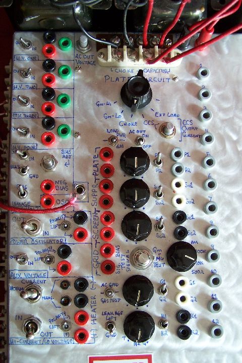
These pictures shows
the most complex part of the whole panel, the switch matrix.
Starting at the top left, you will see
four sections for high voltage power supplies. Each one has a cutoff switch, a
positive and negative socket (because the supplies are lifted from ground
unless one terminal is grounded, giving the option of using them as negative HV
supplies), and a ground socket.
The fifth section down is the negative
bias section. This includes a 10-turn precision pot for bias voltage
adjustment, a voltage cutoff switch, a ground switch (which grounds the output
terminal), and a bias/leakage switch (which changes the output of the negative
voltage between the bias output and the internal leakage circuit).
To
the lower right of the bias section you see the oscillator output (connecting
to the Wavetek) and the ground terminal (which is the star ground
internally).
Then
you will see the power oscillator and aux voltage sections, which have a ground
lift switch, cut in/out switch, and the two requisite terminals.
At
the bottom, you see the heater section. This includes a cut in/out switch, a
current measurement switch and probe sockets (the switch shorts the probe
sockets so the meter can be removed from the circuit), the polarity/ground lift
switch, and four output sockets (which enable one to connect the power
oscillator or the cathode circuit to the heater circuit on filamentary tubes).
Moving to the top center are two
4-position screw terminal strips. These connect to the external capacitor,
chokes, optional external load (which is usually shorted for precision cathode current tests), and the audio output to the Technics amplifier. Just to the
left of those terminals are the potentiometer for the audio output to the Technics amplifier. Just to the right are the banana plug
connections to the dummy load.
Directly
below the screw terminal strips you will find the electrode selection and test
portion of the panel.
Starting
at the top, you find the large selector switch for the loads used in the plate
circuit (which could just as well be arranged for the cathode for cathode
follower tests). The gm-hi and gm-lo are 25W 1% 10 ohm and 100 ohm resistors
respectively. Then there is the choke connection, the CCS (and its variable
bias knob), and the external load connection.
Below
are the load and ac output switches. The load switch is C.O. so you have three
positions: power output load, no load (just the input impedance of the meter,
10M; this is used for gain testing), and a 1M load. The ac output switch cuts
the whole audio/scope/analyzer output so as not to disturb other measurements.
Continuing on, you will see three
similar test section for the plate, suppressor, and screen. Looking at one
section from left to right, you will see two input banana plugs for connecting
to the proper power supply (and/or to other electrodes), a three position
rotary switch for checking leakage (pos 1=test leakage, 2=test tube, and
3=ground electrode), and a switch that selects between two output banana plugs
giving the ability to check two separate sections of a tube easily.
Then you get to the grid and cathode
sections. The grid section has two different inputs, one for bias voltage and
one for an oscillator input. The oscillator is cut in and out via a pushbutton
switch (which I have since replaced with a toggle) for testing gm, mu, power
output, etc. The input impedance to the tube grid is selectable between 500
ohm, 10k, 100k, and 1M. The grid section continues with a C.O. toggle for the
grid giving three positions: gas test, normal test, and ac ground (via a .1uF
capacitor). The gas test connects a precision op-amp set for a gain of 100,000
and supplied by regulated +/-12VDC rails.
Directly below the gas/ground switch
is the leakage ground test switch. This lifts the communal ground for the
electrodes not under test when testing the heater-cathode. The cathode portion
has no input because it is connected internally to ground through a 1% 25W 1
ohm sense resistor. You can easily use this for testing DHT or filamentary
tubes by connecting the output to the negative end of the heater circuit and
lifting the heater ground.
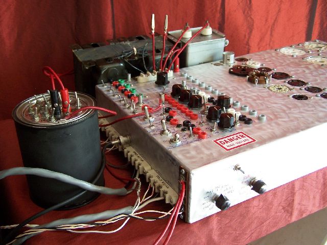
This picture shows the side where all of the test instruments connect. Notice the vintage Millen ceramic screw terminals to stand off the high voltage used. This is an older picture and items have since moved as you will see further down.

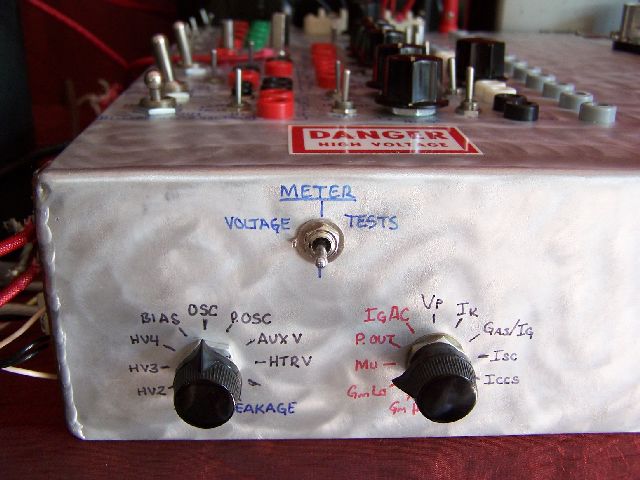
Above is a picture of the meter switches. The toggle switch is C.O. and gives three positions: One for the measuring of equipment voltages (and leakage), an open position so the meter is not exposed to so many different voltages when switching, and one for the measurement of tube parameters and test parameters (like plate voltage or CCS current). The rotary switches are 2P11T ceramic. The one on the left is for equipment voltages, the one on the right for tube parameters.

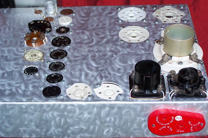
This picture shows
the right half of the test fixture with all of the tube sockets on it. The red
RCA thing on the side is a tube pin straightener, one handy thing to have!
I will list the sockets currently
installed (as you can see, I left room for expansion) in order starting from
the top right going counter clockwise:
B5E Giant 5-Pin –
4-125, 4-400, 803, etc.
B7D Giant 7-Pin –
813
B7A Septar 7-Pin –
829B, 6C33C, etc.
B4D Super Jumbo
4-Pin – WE 212E, Thyratrons
B4F Jumbo 4-Pin –
211, 845, 838, etc.
UV99 4-Pin – only
for the ’99 as far as I know
UV 4-Pin – Great
for all those antique UV based tubes like the 01A and western electric tennis
ball tubes such as the 101 or 102 series
UX4 4-Pin - 01A,
10Y, 45, 50, 866A, 274B, 300B, 2A3, etc.
UX5 5-Pin – 807,
1624, 27, 56, etc.
5-Pin British –
PX4, PX25 etc.
UX6 6-pin – 58,
6B5
UX7 7-pin – 2A7,
etc.
UX7 Medium 7-pin –
1625, 6A6
B7 British 7-pin –
MHD4
B8G Loctal 8-pin –
7C5, 7AK7, etc.
K8A Octal 8-Pin –
6L6GC, 7591, 6B4, EL34, EL37, etc.
B9D/E
Novar/Magnoval 9-pin – I know they’re slightly different, but I only have a
magnoval right now. 8233, 6LQ6, WE 418A, WE 437, etc.
B8A Rimlock 8-Pin
– 6F12
B7G 7-Pin
Miniature – 6X4, 6AQ5, etc.
B9A 9-Pin
Miniature – 12AX7, EL84, 7788, 6094, 6900, etc.
G8A German Stahl –
EF14, VF14, etc.
G5F/7AA/A7 7-Pin
Acorn – 954, 955, 958, 6F4, 6L4
B9G 9-Pin Loktal –
EF50, EF53
12-Pin Compactron – 6JS6, 6K11, etc.
*I have since added a socket for the 152TL/304TL.
I have an entire box full of sockets to add now, but will likely be making a new test fixture in the near future so I have not installed them yet. I am planning to separate the test unit into two parts: transmitting, which would be 1500V or greater on the plate and tubes with plate dissipation greater than 500W; and receiving, tubes that are less than 1500V Plate and 500W Plate dissapation. This requires new power supplies to be repaired, and some to be built from scratch.
As far as other tubes go, I have ways
to test them since I don’t have the proper socket. I use the adapter from my
TV-7 to test 2C39’s. The VT-191 can be tested with the alligator clamp patch
cords I have made up, as can the 833 or any pencil tube. Most lighthouse tubes can be
tested without special socketing arrangements, just one or two clamps, since I
have found many with an octal base.
I
also made a small adapter for submini tubes and nuvistors that is not shown. The
reason I made it an adapter was so there wouldn’t be any arcing over of the
small sockets when testing other tubes at very high voltages.
Boost Transformer, Choke Loads, Dummy Load, and Output Capacitor
Starting at the far left, you will see a Peerless S265-Q output transformer being used in reverse. When doing power output tests, I plug the wavetek into the low impedance side and the high impedance side goes to the test panel. In the configuration I have it in, it will provide a voltage boost of the input voltage*61.4 or *30. This is used for power output tests where the Wavetek's output of 20Vpp will not suffice (which it usually does not).
Next comes a set of Hammond 193M 10H at 300mA chokes switchable between 5H at 600mA or 20H at 300mA.
In the middle is the output capacitor for the choke loads, the resistive power dummy load (described below), and the switchbox for the chokes. You can switch between the hammonds or the UTCs.
On the far right are three UTC LS-90 chokes configured for 150H at 50mA.
Dummy Load
This unit is
comprised of 15 Dale 1% 25W power resistors in series (two make up a 10K
resistor) with a switch that shorts out each individual resistance except the 1
ohm current sense resistor. The total resistance when all are in series is 24.951K. The “V/I” switch on top switches the negative
terminal between ground (which is the case) and the other side of the sense
resistor.
Made in the style of ham dummy loads,
the unit is made out of a 1 quart paint can, spray painted black for better
heat dissipation (black color increases heat dissipation by up to 10% on average), and filled with mineral oil. As you can see from the picture,
I went through great pains to seal all of the switches so that the unit
wouldn’t leak oil. The resistors themselves are soldered in pairs and soldered
freestanding directly to the switches. With the addition of the oil, the unit
should easily take 100W of power with no problem.